
Generally
Activate analog sensor configuration
1. Activate the UI
The prerequisite is this Firmware version 2.3.0(x) (or newer) with Analog Sensor API extension.
In order for your OpenSprinkler to use the analog sensor configuration, the UI configuration must be adjusted.
Please note: There is no manufacturer support (from the USA) for the modified firmware, only German support Support page!
a) OpenSprinkler 3.x:
- Find the IP of your OpenSprinkler by pressing B1
- Open a web browser and go to the SU configuration page of your OpenSprinkler:
http://<ip-address>/su
where <ip-address> is the IP address from 1.
e.g. http://192.168.178.123/su
b) OSPi
- Open a web browser and go to the SU configuration page of your OSPi
http://<ip-address>:8080/su
where <ip-address> is the IP address of your Raspberry Pi.
e.g. http://192.168.178.123:8080/su
SU page:
- There are two input fields on the SU page.

- Enter “https://ui.OpenSprinklerShop.de/js” in UI Source, enter your password (in the delivery state “opendoor”) and confirm with “submit”.
This is necessary because the “official” version does not support these extensions.
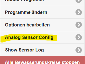
In fact, the OpenSprinkler does not have any GUI (graphical user interface) built in - just an API. The GUI is dynamically loaded via Javascript via this page. - Restart your OpenSprinkler. Now there should be a setting “Analog Sensor Config” under “Options”:
- Android/IOS APP:
– Android: Search for “OpenSprinklerASB” in the Play Store.
– IOS: Search for “OpenSprinklerASB” in the App Store.
2. Facility
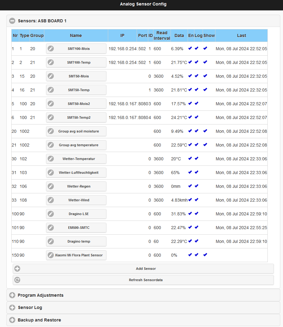
The image above shows an example configuration with one SMT100 and two SMT50 sensors as well as a group configuration.
The area is divided into three parts: sensor, program adjustments and log
3. Sensors
With “Add Sensor” you can add a new sensor, with “Edit” you can edit and change an existing sensor, and with Delete you can delete a sensor.
Press “Add Sensor” and enter the parameters:
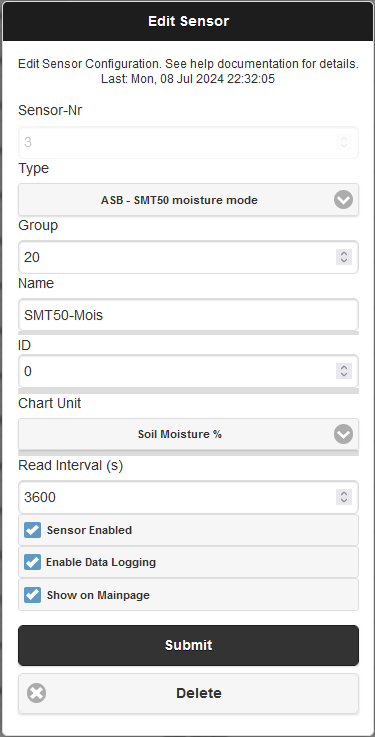
“Sensor number”: Each sensor needs a unique number for management.
"Type": Select a sensor type. More types will probably follow, adding to the list:
- Truebner SMT100 RS485 Modbus RTU over TCP: Connect an SMT100 over the network. To do this you need a TCP to RS485 Modbus converter. The sensor supports two functions: soil moisture (moisture mode) or temperature (temperature mode).
Enter the IP address and port for the RS485 converter, ID is the Modbus ID of the sensor. - OpenSprinkler analog extension board (ASB): 4 variants for converting the input data:
– “voltage mode 0..4V”: No conversion of the input variables, the voltage is used directly
– “0..3.3V to 0.100%” the voltage range 0 to 3.3V is converted to 0% to 100%
– “SMT50 moisture mode”: The voltage range is converted for the Truebner SMT50 – soil moisture mode
– “SMT50 temperature mode”: The voltage range is converted for the Truebner SMT50 – temperature mode
– Likewise for Vegetronix - Special case “ASB – User defined sensor”: Here you can determine the parameters, ranges and offsets of the sensor values yourself
- “MQTT Subscription”: This sensor type is for MQTT sensor values from the connected MQTT server. Define “Topic” (the section identifier) and “Filter” (the sensor value)
- “Remote sensor of a remote OpenSprinkler”: Sensor of another OpenSprinkler in the network. Enter IP+Port for the address of the remote OpenSprinkler. The removed OpenSprinkler must have the same password as this OpenSprinkler. ID is the number of the removed sensor
- “Weather data” – sensors for virtual sensors that receive the values from the weather service
- “Sensor group”: This defines a group that acts like a virtual sensor that can combine several sensors. The summarization happens via
– min: Smallest value of all sensors in the group
– max: Largest value of all sensors in the group
– avg: Average value of all sensors in the group
– sum: Sum of all sensor values in the group
“Group”: The assignment of the sensor to a group. Enter the number of the group sensor here (not a mandatory field, you can also configure this later)
"Name": The name of the sensor
“IP Address” and “Port”: For network devices, the TCP/IP address and port
“ID”: Sensor-specific identification, see “Type”. For the “Analog Sensor Board” this is the connection, i.e. ID=0 for connection number 9, ID=1 for connection number 10, etc
“Read Interval (s)”: Reading distance of the sensor data in seconds (recommendation 300s)
“Sensor Enabled”: Must be active for the sensor to be read
“Enable data logging”: Save the logging data in the sensor log
“Show on Mainpage”: Displays the sensor data on the home page
With “Save” the sensor is saved.
4. “program adjustments” – program adjustments
Here you can assign the sensors to programs.
An “adjustment” means that the sensor values influence the running time of the program, so for example the weather control can be shown here as a % value, a program can run longer or shorter.
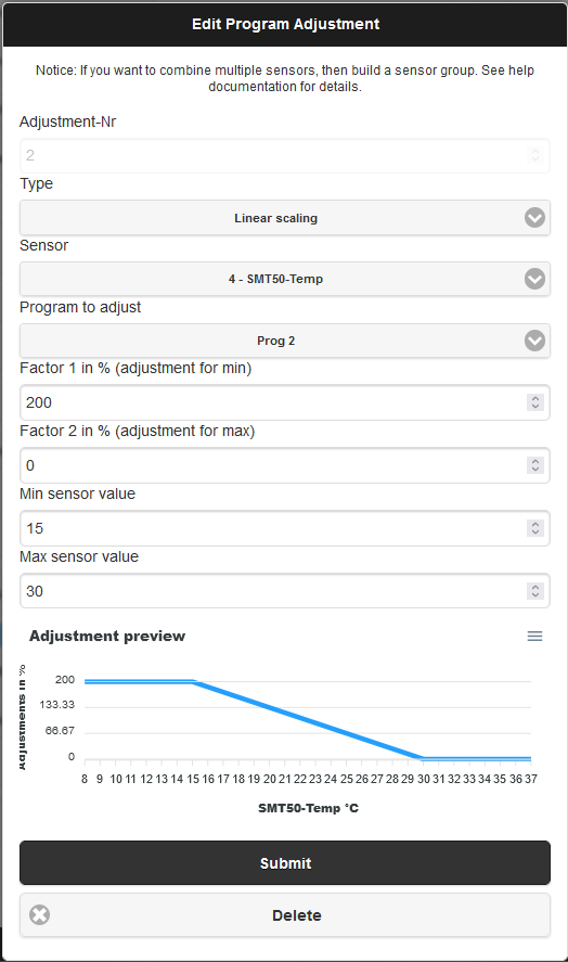
A program adjustment can only ever be assigned to one sensor. If you want to assign multiple sensors to a program, create a sensor group and use it for customization. Alternatively, you can also define several program adjustments and assign them to the same program, but then the program adjustments are multiplied (e.g. adjustment A: 90%, adjustment B 110%, then the effective adjustment is 0.9 x 1.1 = 0.99 corresponding to 99%).
“Adjustment number”: Unique number for customization.
"Type": The type defines how the sensor data is converted for program adjustment:
– “No Adjustment”: No adjustment is made, e.g. to temporarily switch off
– “Linear Scaling”: The adjustment is completely linear: “Min and Max Sensor value” define the range of the smallest and largest sensor values, e.g. 30% and 60%. “Factor 1 and 2” define the adjustment factors, where the values represent a proportional adjustment. For example, if you want an adjustment value of factor 200% with a minimum sensor value of 0, then enter “200” in “Factor 1”. In “Factor 2” the value for the Max Sensor Value corresponds
– “Digital under min”: If the sensor value falls below the min sensor value, then factor 2 applies, otherwise factor 1
– “Digital over max”: If the sensor value rises above the max sensor value, then factor 2 applies, otherwise factor 1
"Sensor": Select the sensor for the sensor data
“Factor 1/2” and “Min/Max Sensor value”: See Type for the adjustment values
5. Log
With “Clear Log” you can delete all log data. Download the log with “Download Log”.
You can also use the API function to read out the data directly in JSON format, filter it and then delete it.
The description of the API functions is currently available available here.
“Show Log” shows the last 24 hours:
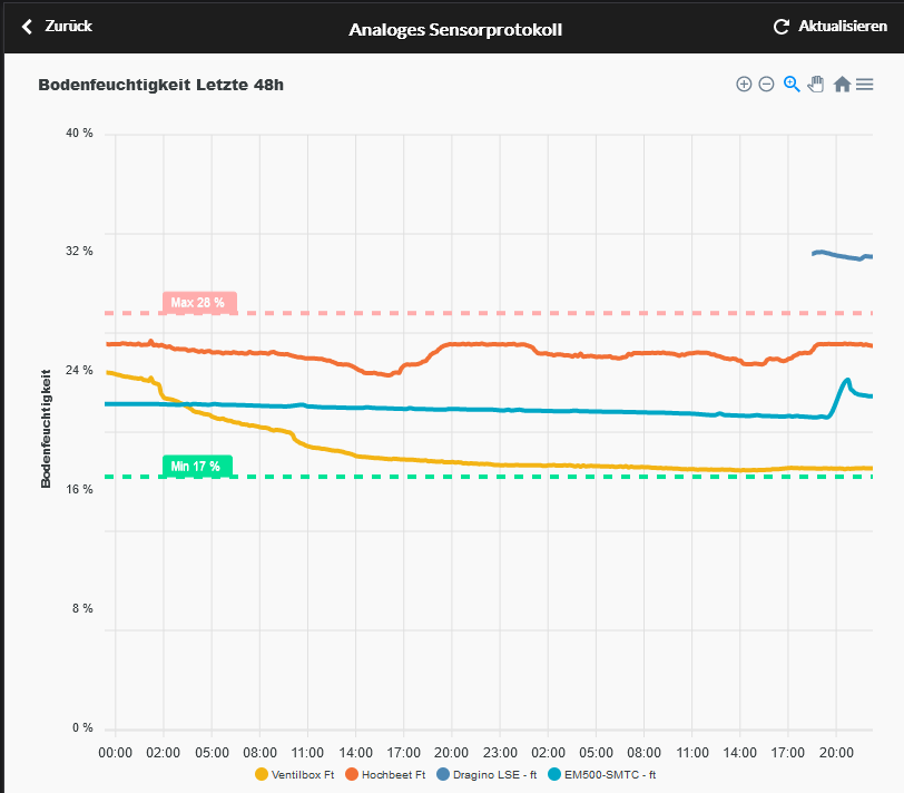
The dashed “Min” and “Max” lines show the adjustment range created under “4. Program adjustments”.
Sensor setup
1. Types of facilities
The current software can use 4 types of sensors:
- digital sensors via the SEN1/SEN2 connections (classic sensor inputs)
- analog sensors via the A2D to the digital sensors (switching limit simulates digital sensor)
- analog sensors via that new analog sensor board (direct connection to a sensor input)
- analog sensors via TCP/IP RS485 Modbus converter (Truebner SMT100 RS485 Modbus version)
No external configuration is necessary for the first 3 variants; everything can be set directly in the OpenSprinkler app.
Only the last two variants can be recorded via the new sensor log and displayed in a diagram!
2. Analog sensors via TCP/IP RS485 Modbus converter
In order to integrate an RS485 Modbus sensor, an RS485 Modbus converter must be accessible in the same network via its IP address.
You can find out detailed information about RS485 and Modbus here.
You can find an example configuration using the USR-W610 and Truebner SMT100 RS485 Modbus here.
The “Waveshare RS485 to RJ45 Ethernet Converter Module” is recommended for the top-hat rail. Info here.